Winding and pumping engines at the smaller pits
The biggest problem facing the miners at Poynton and Norbury was removing water from the workings and this was to increase as the mines were sunk to greater depths and when many outlying pits were closed. In the early days, primitive methods using soughs and waterwheels were sufficient to enable work to continue, 1 but during the eighteenth century deeper workings led to the introduction of atmospheric beam engines to drain the collieries. 2
Poynton Collieries were a major undertaking by the end of the eighteenth century and steam technology was being introduced not just for pumping water but also for raising coal. Such innovations were worthy of note in the press and in 1794 one such engine was recorded.
"An engine (Only an eighteen inch cylinder) to wind up coal is erected at Sir George Warren's Colliery in Cheshire. It raises two tubs laden at a draught, which reciprocally pass two empty ones without a possibility of touching each other, and discharge into a moving carriage that conveys the coal into carts. The same quantity is drawn in eight hours as employed four horses". 3
This wonderful new engine was soon followed by a new pumping engine close to Norbury Hollow which was erected by Nathaniel Wright during 1795. It was probably built by Bateman and Sherratt of Salford and incorporated a separate condenser, thus infringing James Watt's patent. 4 During 1796 however, the engine was discovered by James Lawson who was acting as agent for Boulton and Watt and he wrote to James Watt junior on 25 March 1796:-
"I have now nearly finished my espionage, having just seen the engine on (a) coal mine near Bullock's Smithy which has an air pump and condenser exactly similar to Boulton and Watt's, only like all the rest, well concealed.
In going to see it I observed very near it a small winding engine with conductors in the pit same as you saw at Kippax. This engine I said I came to see. 5
I found at the place the landlord of a neighbouring ale house half drunk (being Good Friday and consequently a holiday), who sent for the engine man (and also for some ale) to set the winding engine to work. In the meantime I examined the pumping one - it is (a) 40 inch cylinder, 6 foot stroke and has been at work just thirty weeks this day, the landlord remembering well the day it was set to work. It was working well, about 12 strokes per minute." 6
Nathaniel Wright was either unable or unwilling to pay the premium which Boulton and Watt subsequently demanded and converted the engine back to the old atmospheric principle.
By 1826 Watt's patent was long expired and his separate condenser was in use on engines at several of the Poynton pits. In fact almost all the pits were steam worked by this time. All the engines except one were beam engines using atmospheric pressure to provide the power. The winding and pumping machinery in use in 1826 is listed below: 7
| Steam Engines | Other Winding Machinery |
||||||||
| Pit | Separate Condenser | Use | Cylinder Dia (ins) | Pit |
Type |
Diameter (ft) | |||
| Worth Clough | Yes | Pump | 45.125 | Worth Engine |
Horse Gin |
6 | |||
| Clough Deep & Rise | Yes | Winding | 19 | Higher Smithfield |
Horse Gin |
12 | |||
| Clough Sidebottoms & Lucky | No | Winding | 23 | Lane Side |
Horse Gin |
||||
| Hig Meadow (Anson) | No | Winding | 18 | Horse Pastures |
Horse Gin |
||||
| Gees | No | Winding | 28 | Gees New |
Horse Gin |
||||
| Gees New | Yes | Winding | 19.5 | Gees |
Turn9 |
11 | |||
| Higher Smithfield | Yes | Winding | 16 | Waterloo |
Turn |
||||
| Lower Smithfield 8 | Winding | 18.5 | |||||||
| Accommodation | Yes | Winding | 20 | ||||||
| Waterloo | Yes | Pump | 40.75 | ||||||
| Waterloo | Yes | Winding | 22 | ||||||
| Horse Pastures | No | Pump | 36 |
|
|
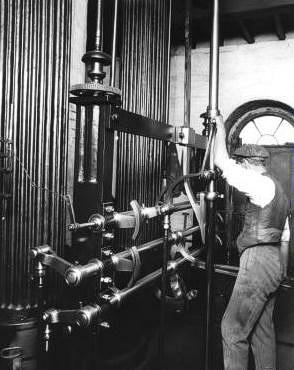
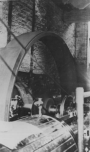
| Hand operated valve gear for starting the Cornish pumping engine at Lady Pit, 1926. |
The collieries were obviously being worked in an efficient manner using modern equipment and that this policy was continued is evident from the list of engines contained in the 1847 Colliery Report. This recorded 18 engines of which 15 were for winding coal, 2 for pumping and 1 driving the saw mill at Towers Yard. These included several new and powerful engines including a 72 horse power pumping engine at Lord Pit and a 70 horse power winding engine at the Tower Pit. Only the older pits such as Dingle and Victoria retained their older and less powerful machinery of 12 and 16 horse power respectively.
The increasing depth and size of the workings led to yet more pumping engines being installed and by 1857 water was pumped at six pits - Oval, Lord, Horse Pasture, Lower Vernon, Waterloo and Canal. The Canal Pit engine was winding coal as well as pumping water for 3½ hours per day whilst the Lower Vernon engine was raising water 48 yards from the 10 Foot Seam for four days a week. It was only in 1875 that the main pumping load was concentrated at Lady Pit with the erection of the huge Cornish pump "Big Ned".
Pumping at Canal Pit continued until the closure of the collieries using a
horizontal steam engine with a single cylinder 20 inches diameter by 30 inches
long. This replaced an earlier engine which was destroyed when the engine house
burned down in the late nineteenth century. The drive was geared 1 to 3 to two
horizontal rods and two L legs working over the shaft. These rods and legs were
painted red and gained the pit the nickname "Redlegs". Water
was raised in three lifts: Top Lift 50 yards, Middle Lift 50 yards, Bottom Lift
45 yards. This engine could also wind with one rod pumping although to ride
in the cage was not always pleasant. As one man said: "It was a nightmare
to go down especially when wet because the brake drum was outside(the engine
house) and sometimes you could stop within ten feet and sometimes you couldn't."
Lord and Lady Pits. SJ 930/1 834
The Lord Pit was the smaller of the two shafts on this site, sunk 114.5 yards
to the Five Foot Seam and was used mainly as a pumping shaft although some coal
was raised in the nineteenth century. It was probably sunk in 1835 when a 72
horse power beam pumping engine was installed. Coal getting ceased soon after
1857 and the pumping engine worked on for a few years. In 1891 the pump house
was made into a water tower and finally collapsed during the 1920s.
 |
Lady Pit with its shaft 10 feet in diameter was presumably sunk along with Lord Pit in 1835. In 1847 it was working the Four and Five Foot Seams and had a 32 horse power winding engine. The next year it was sunk to the Gees Seam at a depth of 164 yards and some 1 20 men were working this seam in 1857, producing about 3600 tons of coal per month. Production stopped in 1862 and it was not until 1866 that work commenced to sink the shaft to the Accommodation Seam which was reached at a depth of 222 yards 2 feet 3 inches. This work was part of a scheme to concentrate pumping at the Lady Pit and resulted in the erection of "Big Ned" between 1870 and 1875.
This engine was originally built in 1853 by Perran Foundry for the Perran United Mine in Cornwall. In 1860 it was moved to North Downs and Wheal Rose United Mines to pump from Wheal Messer Shaft. After these closed in 1869 it was purchased by Harveys of Hale in 1870 and sold soon after to Poynton Collieries being despatched in pieces by ship to Liverpool. 10
The engine was of the Cornish condensing beam type with a cylinder 80 inches in diameter and a stroke of 10 feet. The pump stroke was also 10 feet. The beam was in 2 plates 30 feet long and had a total weight of 30 tons. Four Lancashire boilers supplied steam at 45 p.s.i., reduced to 25 lbs. at the engine. It pumped at five strokes per minute raising 190 gallons of water per stroke. Water was raised in two lifts, the Bottom Lift being 129 yards with 20 inch bucket, whilst the Top Lift was 119 yards with two 17 inch bucket sets. Towards the end of its life this engine would not work automatically and the hand gear used for starting had to be operated all the time that it was pumping. The capstan engine to lift 80 tons had two 10 inch cylinders and was made by F. Scott.
 |
 |
|
|
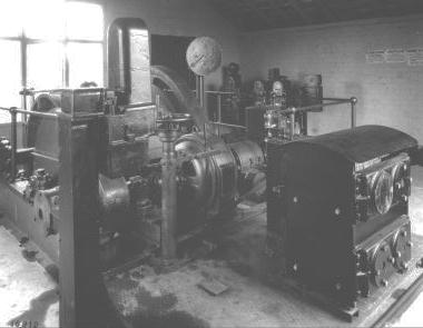
Lady Pit electric winder, 1926
|
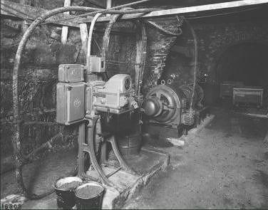
Lift pump at bottom of Lady Pit, 1926. This is the only underground photograph of Poynton Collieries that shows an actual coal seam. |
Preparations to raise coal again at Lady Pit were started during 1889 when
a new winding engine and screens were installed. The winding engine was erected
at a cost of £669 by Stanley and Davies of Hyde and had two horizontal
cylinders 22 inches in diameter with a 4 foot stroke. It wound a single cage
in the Lady Pit shaft which was counterbalanced by a cage filled with loaded
tubs in the Lord Pit shaft.
Coal production ceased here in 1907 and when the electrification scheme was
introduced in 1926 the steam plant was superseded by electric pumps and winder
supplied via a 2200 volt overhead line from Park Pits. The winder, in a new
building, was manufactured by John Wood & Sons Ltd. of Wigan and powered
by a British Thomson Houston (BTH) 20 horse power motor. It wound much more
slowly than the steam engine but this was of no consequence now that coal was
no longer produced here.
The Cornish pump was retained on standby whilst pumping was transferred to two
Worthington Simpson high lift centrifugal pumps. The Bottom Lift was powered
by a 75 horse power motor driving a five stage pump with a capacity of 224,000
gallons per hour. The Top Lift pump was similar and powered by a 115 horse power
motor.
Since the pits closed in 1935 all traces of the electric plant have disappeared at Lady Pit whilst the 1889 winding engine house and the capstan house to the beam pump have survived.
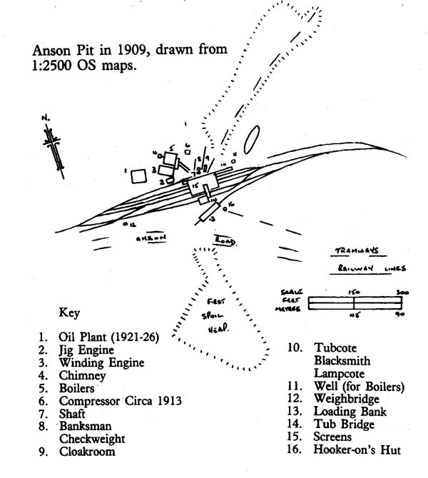
Anson Pit. SJ 940 835
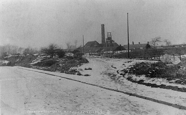 |
| Anson Pit c1905. Note tub road running in front of fence |
 |
|
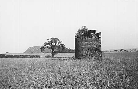
| Walker Pit, 1953. This early pit was eventually used for furnace ventilation. Anson Pit spoil heap in background. |
The Anson Pit was originally known as Hig Meadow Pit and may have had a shaft
situated just to the east of the Anson bungalow. In 1826 the winding engine
was of the Newcomen atmospheric type having an 18 inch diameter cylinder, spur
gears and flat rope drums fixed up in wood framing with a wrought iron boiler.
There were 1088 yards of rail roads underground and 22 coal tubs. It also had
its own carpenters' shop.
By 1847 the pit was referred to as Anson or Lower Anson and employed 36 men
and six boys underground working the Gees Seam at a depth of 132 yards. The
winding engine was 16 horse power. In 1853 it was deepened to the Accommodation
Seam at a depth of 191 yards whilst coal was also raised from the Reform level
which entailed the cage being stopped at 147 yards. By 1856, 170 tons of coal
per day were being raised.
Increased output was limited by the fact that the shaft was only 10 feet in
diameter and could only take one cage, there being insufficient room for two
to pass. The problem was neatly solved by Greenwell around 1866 when a bypass
was constructed at the halfway point in the shaft. The bore was widened and
fitted with iron conductors at this point and the two cages sidestepped each
other in what must have been an odd experience for the miners riding to work.
In conjunction with this work, a new winding engine was erected to replace the
old machine which was reported to be in a dilapidated condition. This engine
was set to work in May 1869 and performed very well until the colliery closed.
It had two horizontal cylinders 25 inches by 60 inches with double beat valves.
The drum was 14 feet in diameter for round ropes, raising two tubs per cage
on one deck. An engine was later installed on the surface to haul sets of eighteen
tubs for 900 yards up a 1 in 7 brow in the Accommodation Seam. It had two horizontal
cylinders 15 inches by 30 inches geared 1 to 4 to a 5 feet diameter drum. Steam
was supplied to both engines at 30 p.s.i. by three Lancashire boilers.
Compressed air coal cutters were introduced at the Anson Pit in 1922 to work the top block of the Accommodation Seam, but the pit was closed four years later and electricity was never used. 11
Ventilation for the Anson Pit was supplied by a furnace at Horsepasture Pit, SJ 941 841, and other ventilation furnaces were at Walker Pit SJ 937 836, Venture Pit SJ 947 831 and Higher Canal Pit SJ 949 839.
An interesting development at Anson Pit during the 1920s was the erection of a plant to extract oil from coal by a company unconnected with the collieries. This comprised a four storey building filled with retorts etc. and experiments were carried out with local and foreign coal as well as peat but it was closed by 1926 and operations transferred to Scotland. For several years this plant lay derelict with many barrels of oil lying around it.
 |
Park Pits. SJ 935 846
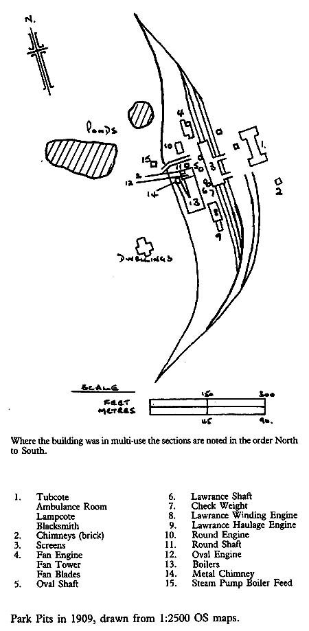 |
The Park Pits were sunk towards the western boundary of the Poynton coalfield
and they proved to be prolific producers of coal. In addition to the dozens
of shallow workings in the area there was also at least one larger shaft on
the site before the railway age but it was not until 1845 and 1846 that work
commenced in sinking two shafts 198 yards in depth to recover the Four Foot,
Five Foot and, later, the Gees and Reform Seams. The smaller of these shafts
was the Round Pit whilst the other, with its unusual shaft 12.5 feet by 9½
feet was the Oval Pit.
Completing and expanding the workings took over ten years and in 1856 the Oval Pit was only drawing 30 tons of coal per day although this was partly due to the fact that the engine was almost fully employed in pumping water which was running in at 300 gallons per minute. Round Pit was raising 126 tons per day with its 40 horse power engine. During the next year the redundant 60 and 80 horse power winding engines from Albert and Quarry Pits were moved to Oval and Round Pit respectively and the original 70 horse power Oval Pit winder was left to pump water.
In 1875 a new winding engine was erected for the Oval Pit at a cost of £3950
including engine house, three boilers and pulley frames. This engine was made
by J.D. Leigh of Patricroft and had two horizontal cylinders 30 inches by 72
inches with four Cornish valves to each cylinder and plain winding drums of
cast iron lagged with wood 16 feet in diameter for round ropes.
Sinking the Lawrance Pit was started in 1884 and the 13 feet diameter shaft
reached the Accommodation Seam at a depth of 310 yards. The winding engine that
had been erected in 1875 was now used to wind the Lawrance Pit which may explain
why the new shaft was sunk only a few feet from the Oval Pit. The two cages
in the new pit held four tubs each on two decks and a wind, including changing
tubs, took one minute. A haulage engine was also erected behind the Lawrance
engine house to wind tubs up a downbrow in the Accommodation Seam. It had one
horizontal cylinder 10 inches by 20 inches gearing 1 to 5, and a 4 foot drum.
The rope passed underneath the winding engine before descending the shaft.
Winding at the Oval Pit was transferred back to the original engine of 1845. This interesting engine was built by Thomas Murray of Chester-le-Street and was of the vertical single cylinder condensing type with the drum placed above the cylinder and also a pumping beam. The cylinder was 47 inches diameter 71 inches stroke with four double beat valves. Winding drums were 11 feet diameter for flat ropes and raised three 6 cwt. tubs in each cage on three decks. In 1856 it had been pumping at 14 strokes per minute for 14 hours per day from both Oval and Round Pits and raising 433,440 gallons of water per day. The lifts were: Oval Pit, first lift 64 yards, second lift 59 yards. Round Pit, first lift 48 yards, second lift 33 yards. The stroke was 6 feet 6 inches and the working barrier around 13.5 inches. Pumping with this engine was presumably stopped in 1885 when it was put back to winding at what was one of the main shafts. 12
This engine survived at work until the closure of the Oval Pit in 1928 and was always awkward to handle. It had hand valve gear for starting and would sometimes swing back and to. Occasionally the engine man would have to take a big prop to push it off top or bottom dead centre.
By 1892 a Tangye type pump had been placed in the 10 Foot mouthing of the Round Pit. It had one cylinder 18 inches by 36 inches acting directly on the 9 inches by 36 inches double acting pump which forced the water up to the condenser on the Oval Pit winder. It was working four hours per day in summer and 18 hours per day in winter. At the bottom of the same pit there was a hydraulic pump which derived its power from the lodge room of the 10 Foot through a vertical height of 250 yards of 2 inch pipes. The water cylinder was 4½ inches diameter with a 4½ inches ram which worked five hours per day forcing water to the 5 Foot lodge room whence it ran to Lady Pit.
During the sinking of the Lawrance shaft the Round Pit was deepened to 310 yards and used as the upcast and emergency shaft for the new pit. Ventilation was provided by a Schiele fan 8 feet in diameter, driven by a horizontal engine with a cylinder 20 inches by 30 inches and geared by leather belt and two pulleys in the ratio 1 to 3.6. The speed of the engine was 70 r.p.m. and the fan 253 r.p.m. A duplicate engine was kept in readiness to allow for breakdown and maintenance and the whole engine was nicknamed 'Mary'. A small two cylinder slide valve winding engine with 7 feet to 8 feet diameter drum was installed for the Round Pit but usually only one cage was kept on. In 1892 steam for the Park Pits was supplied by seven Lancashire boilers at 60 p.s.i. This was reduced to 20 p.s.i. for the Oval Pit winder.
 |
 |
|
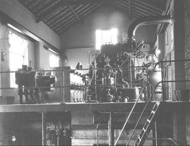
| Fan engine, Park Pits, c1930. Note belt drive from flywheel to fan. | Interior of power house at Park Pits, 1926. Turbo-alternator in centre. This building was later filled with brickworks machinery. |
The first screens at Poynton Collieries were erected by G.C. Greenwell in
1863 and they were of simple construction:
1st Screens 1 inch width -coal passing over to be sold as House Coal.
2nd Screens 0.5 inch width - coal passing over to be sold as Burgy.
What passed through to go to the engines and for coke making.
In 1864 these screens were said to be answering well and the system was to
be extended to the other pits. They survived until the Lawrance shaft was sunk
when a greatly improved set of screens was built with several railway sidings
beneath.
"Four screens are erected at Park Colliery designed and patented by Mr. G.C. Greenwell jnr. These are 32 ft. long by 5 ft. wide with ten revolving chains; the fourth is 32 ft. long by 4 ft. with seven revolving chains. The screen itself is divided into four sections of 8 ft. length, each of different mesh. A hopper under each section receives the different sizes of coal as it falls through the bars from whence it is run into trucks, for which four lines of rails are provided besides one for the large coal. The chains are the chief feature of this patent; they move around the pulleys at the top and bottom of the screen and run between the bars in their descent, the effect of which is to draw the coal gradually forward towards the bottom. The coal is cleaned by one man and three boys at each screen as it passes down. The fall of a screen & 2 ft. from top to bottom. The sizes of coal made at each, from the tap downwards, are as follows:- slack, rough slack, nuts, lumps or cobbles, and large (which passes over all). There are two screen engines each with a 10 in. cylinder geared 1 to 5, one engine serving two screens. The chains make twelve revolutions per minute." 13
The final changes to the arrangements at Park Pits took place during 1926
when British Thomson-Houston Co. Ltd. of Rugby, under the direction of Messrs.
Ravenshaw & Dyer, consulting engineers to Poynton Collieries, undertook
an extensive electrification scheme centred on these pits. Power was generated
at 2200 volts, 3 phase, 50 cycles by a 625 Kw 3000 r.p.m. B.T.H. Curtis mixed
pressure turbo alternator. This was housed with the main switchboard in an extension
of the main compressor house. The three stage turbine could use high pressure
steam at 150 p.s.i. down to 100 p.s.i. or low pressure exhaust steam from the
Lawrance winder and two compressors. Preference was given to low pressure steam
down to 16 p.s.i. Power lines were run to Lady Pit and Towers Yard.
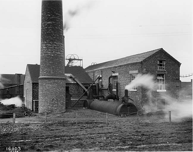 |
| Exterior of powerhouse, Park Pits, 1926. Note old boiler used as accumulator. |
Worthington Simpson multi stage high lift centrifugal pumps were installed running at 1450 r.p.m. Connections were made to the existing suction and rising mains so that steam power could be used in emergency. At Park Pits the electrical equipment underground comprised: 10 Foot Seam - pump with 15 horse power motor. 5 Foot Seam - 7 inch pump with 160 horse power motor, output 320,000 gallons per hour. Accommodation Seam - pump with 50 horse power motor and haulage with 50 horse power motor. On the surface the screens were electrified with two 20 horse power motors for the main drives and two 10 horse power motors for the conveyors. A 20 horse power motor was also installed for the dirt tips haulage. Estimated savings in coal consumed for colliery services were to be about 50% and 30% had been achieved by 1927. 14
By 1928 an aerial ropeway to the dirt tips was installed using electric drive. This had two trestles and a tower of about 120 feet, pivoted at the bottom and fastened by two guys. Two cages were attached to the 1⅛ inch running rope and each carried one loaded tub to the tip where it was automatically turned over and emptied.
Methods of working
A comprehensive description of the methods of working the coal at Poynton
was given in the Colliery Guardian during 1892. The Accommodation Seam
was worked on two separate systems. The top coal was worked first on the bord
and pillar or Lancashire system and then the middle and bottom coals were got
by the longwall system. The Five Foot Seam was worked exclusively by bord and
pillar, as was the Four Foot Seam. Finally the Reform Seam was got entirely
by longwall, this being the only coal at the time requiring explosives for breaking
it down due to its sticking to the roof. The explosive "Ammonite",
fired by electricity, was used for ripping down stone in the gateways.
 |
|
| Lancashire Bord and Pillar system of coal extraction as used in Poynton |
In the Poynton Collieries the form of bord and pillar working was as follows, working back from the boundaries:
"At the far end of the levels jigbrows are driven to the rise 110
yards or more, and l00 yards apart. No. 1 jigbrow will be driven up, say, 100
yards distant from the boundary. From this brow the bords are started at right
angles, on level course, 2 yards wide, with pillars between of 20 yards. Usually
five bords are driven from a jig brow, which would serve to take away a breadth
of 132 yards of coal but the breadth varies according to circumstances. The
highest bard having reached the boundary, the wide work is then commenced at
the far corner from the miner and of the fifth bord, by driving a stall 6 yards
wide up to the limit of 20 yards. Afterwards, a second stall is taken alongside
and, at the same time, a stall is commenced from the fourth level. The same
process is repeated down to the main level, when six stalls will be in operation,
one 6 yards in advance of the other, from the top downwards. The closure of
this section or panel will be made at the lower corner next the fig brow. Before
this has been effected a second jig-brow will have been driven up and five bards
extended inwards to the first jig-brow, so as to keep up the coal production
and the employment of miners at a uniform rate."
The longwall system was somewhat different.
"Gateways are formed to the rise as the excavation of the coal proceeds,
these being about 30 yards apart supported on each side by packwalls 3 yards
in width; the material to build these is got from the rippings of the top for
gateway extensions. A middle packwall is also built where material is at hand.
The hollows thus left of 10 yards width, are filled in, more or less completely,
with refuse from the holings and shale bands in the seam. The settlement of
the roof is thus moderated; where buildings on the surface are to be supported
and the production of large coal is a consideration, this principle of getting
coal is to be preferred to the former." (ie. bord and pillar) 15
References and Notes
1. For details of some of the soughs and waterwheels see Poynton
Collieries: General history of mining to 1831.
2. The atmospheric beam engine used very low pressure steam which was condensed
in the cylinder by water jets, thus forming a vacuum. Atmospheric pressure on
the top of the piston pushed it down thus raising the other end of the beam
and activating the lift pumps attached to wooden rods at that end. The weight
of the pump rods then pulled the beam back down, raising the piston and drawing
steam into the cylinder ready for the cycle to start again. The first such engine
in the area was at Norbury before 1764 (see Poynton
Collieries: General history of mining to 1831.).
3. Derby Mercury 16.2.1794.
4. The separate condenser was a device which took the water sprays away from the cylinder of the atmospheric engine with a consequent increase in efficiency. Boulton and Watt held the patent for this improvement and charged a premium for its use. The patent was infringed by several manufacturers who produced so called "pirate" engines for which no premium was paid.
5. This was an early use of pitshaft guide rails, which had been patented by John Curr of Sheffield Park Colliery in 1788.
6. For further details of this episode see Chaloner W.H. "The Cheshire Activities of Matthew Boulton and James Watt of Soho near Birmingham 1776-1817" Transactions of the Lancashire and Cheshire Antiquarian Society, Vol.LXI 1952.pp. 129-131.
7. Inventory in deed of purchase of lease of Poynton Colliery, Stockport Public Library, AX 1137.
8. This engine was probably a true steam engine using steam pressure and reciprocating motion rather than a beam.
9. A turn was a hand operated windlass situated directly over the shaft.
10. Barton D.B. The Cornish Beam Engine. Bradford Barton. 1965, pp. 65-67. This engine is incorrectly noted as having been sold in 1870 to Greenwell Colliery, Lancs.
11. Several types of coal cutters were used at Anson and Lawrance Pits. One had chain driven picks on a 5 foot jib. Mavers and Coulson of Glasgow supplied a piston type cutter which had a 6 foot tapered bar which ran in and out on a worm and cleared itself. There was a star pick ("Banjo") at the end. Later a turbo engine type was used at Lawrance Pit where the compressor house was situated next to the boilers and later incorporated into the turbo alternator house.
12. For photographs of similar engines to this made by Thomas Murray see Watkins, G. The Steam Engine in Industry - 2, Moorland, 1979.
13. The Colliery Guardian 9.9.1892. For a fuller description of Greenwell's patent screen, see Transactions of the Manchester Geological and Mining Society, Vol. 20 1889, pp. 440-444.
14. A full description of the electrification scheme appears in The Colliery Guardian 11.3.1927. pp. 561-563.
15. The Colliery Guardian 9.9.1892. p.456,
For further information see:
Poynton A Coalmining Village; social history, transport and industry 1700 - 1939, by W.H.Shercliff, D.A.Kitching and J.M.Ryan, published by W.H.Shercliff, 1983. ISBN 0 9508761 0 0
Poynton Collieries: 1890-1935 The final years
Poynton Collieries: Subsidiary Industries
Last updated 7.6.14